Go to... | Start A New Topic | Search | Notify | Tools | Reply To This Topic |
| Fuel Tank Tips | Login now/Join our community |
| First Month Member |
All Barths are not the same, but perhaps some of this information is useful to some. I decided to replace my old (and presumably) brittle fuel lines with newer spec lines for today's alcohol-laced fuel. I also wanted to relocate the fuel pump to a position where an unscheduled roadside repair would be less difficult. Barth mounted it above the tank where even Plastic Man couldn't reach it. And, a recent on-the-road genset vapor lock calls for moving the genset electric pump outside the warm genset bay to a cooler location to assure the fuel lines in the hot genset bay are pressurized, mandating a higher boiling point. Yeah, I know, if it ain't broke, don't fix it. However....................... My gasser has the tank mounted to the frame by steel cradles on 7/16 NF studs welded to the frame. First step is to squirt them ahead of time with PB Blaster, Kroil, or your favorite mouse milk. Next step is to chase the threads with a die or thread chaser. I have a cobbled-up die holder that allows it to be driven all the way up by a power driver or rattle wrench. After the jam nut is removed, run the chaser or die all the way up to get the threads that were hidden the first time. Then remove the mounting nuts. It is a good idea to hold the rod with a Vise Grip down low, so the vise grip takes any twisting force. This will prevent twisting the rod off up at the frame, where replacement could be a problem. The nuts are self-locking on mine, and turn hard. So it is a giant pain to remove with an open end or box end wrench in the limited swing space. An extra-deep socket or a dog bone or gearwrench is an absolute must. An extra-deep socket on a rattle wrench is best. If you don't have an extra-deep socket, use the wrench to get the nut down far enough to use a deep socket and a ratchet, rattle wrench or drill driver. Be prepared for surgery. That may be only cutting a nut off with a die grinder or cutting the stud off. Cutting the nut is best. Try to make a cut that almost goes through, but not quite. Then a heavy, square-shanked screwdriver can be twisted with a Crescent wrench to split the nut. If you cut the stud off, try to leave enough stud to mount a coupling nut to the remainder. This will allow you to replace the part you cut off. Chances are the cradle will have to be rebent a little on that side to accommodate the space taken up by the coupling nut. Getting the right tools and parts lined up ahead of time will make the job much easier, even if surgery is not necessary. Perhaps the hardware store will let you return the coupling nut. 7/16 NF coupling nuts and threaded rod can be hard to find when your Barth is hors de combat Once the tank is ready to drop, use a floor jack, transmission jack or motorcycle/ATV lift to lower it enough to get up there and disconnect and mark things. If you have none of the above, just crib it up with scrap lumber and remove the boards one by one to lower the tank the ground. (I have removed transmissions and transfer cases this way, as well). When the tank is completely out, chase the threads all the way up, just in case something goes wrong next time you drop the tank, and you need to do the coupling nut thing. I install a coupling nut all the way up just in case I need it if problems arise in the future and I need it to splice in a new section of rod. I put a couple of brass nuts up on the rod, and double nut them to give me something to grip next time to avoid any breakage farther up. I also use brass nuts to hold the tank up. Install with anti-seize or Lubriplate (white lead from a paint store is a decent substitute) and then apply several spaced applications of LPS-3 to assure corrosion protection. Then slide some tight-fitting vinyl tubing up over it to add another layer of corrosion protection. Or shrink tubing. You might also consider cutting some conduit tubing as spacers to avoid the bother of running the nuts all the way up that threaded rod. This will also aid removal in the future. Sure, enough, I found the rubber lines to be somewhat elderly and deteriorated. 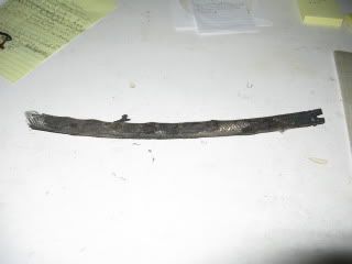 The filler vent line had cracked completely through, with the pieces held in alignment only by the reinforcing braid. It's brittleness made me suspect that it might be heater hose, rather than gasoline vent hose. Its only marking was 5/8" In addition, 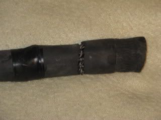 The vapor recovery return line was attached to the filler vent line by a 3/8 hose that was forced over a 1/2 inch nipple, resulting in serious cracks. I noticed that the 1/2 inch nipple on the fitting had been welded partially shut. 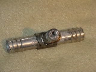 My WAG on this is that they were trying to prevent an overfilling event from causing fuel to go up into the charcoal canister and then flooding the carb with charcoal granules. Yes, this already happened to me. On a Friday night leaving town on a weekend trip. Roadside Quadrajet disassembly is no fun. I now have an inline filter between the charcoal canister and the carb to prevent a reoccurrence, but I have now rerouted the lines to prevent such a problem from even starting. My guess here is that Barth spec'ed the tank for an earlier emissions system, without the charcoal vapor purification system, and, rather than add another vent fitting to the top of the old spec tank, just tee'ed into the fill vent. Truly a bodge. I found poor internal electrical connections in the fuel level sender. One, in particular, was an example of very poor design...........a brass tab riveted on top of the aluminum mounting plate. Brass and aluminum in the presence of road spray and atmospheric moisture is very, very dumb. There was another internal connection of aluminum to aluminum that had just begun to fail, as well. I had to use a megger to check it properly, but it was starting to go. I just made an end run around them by running a jumper to a new screw that went from the jumper through the top plate up to where it became the new connection for the ground circuit. The other end of the ground circuit, where it is connected to the frame, also got a good cleanup and a new terminal. And, of course, the external connections get a shot of LPS-3 at the end. 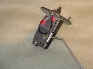 The tank looked decent inside, but I poured a quart of Transpo and a bunch of small sharp garden rocks in it and plugged the openings. I put the tank in the back of the truck and we drove it around for a week. I managed not to get stopped for my swerving and hard starting and stopping. It ended up very, very clean inside. The sending unit is a Medallion B-1321 90 ohm unit, very common in hot rods and boats. It also9 mates with the OEM Chevy gauge. I had a sending unit gasket in stock from my boat parts stash. It is a Delco 1516395. West Marine http://www.westmarine.com/weba...10443&classNum=11324 has it. It is their number 8979106 and Moeller # 35728-10. Old GM vehicles also used that gasket until they went to the twist lock fitting on top of the tank. NAPA has a similar gasket on their site under the number BK 7012378 http://www.napaonline.com/Sear...K_7012378_0126471382 but good luck at the counter. The parts professionals were unable to convert the Delco number or even find the NAPA number that is on their site. It is a standard SAE design. Titeseal is a good gasoline-proof sealant for this. Or Hylomar or black Permatex. It's a good thing I got in there, as the suction hose on the OEM electric pump was very loose on the nipple. It could be rotated quite easily, and the two Corbin clamps could also be rotated on the hose just as easily. It was only a matter of time before the fuel pump started sucking air. I believe the Corbin clamps were snug when installed, but were a little too large to compensate for the age-related shrinkage and cold flowing of the rubber line. The genset fuel line was 5/16 line forced over a 3/8 nipple. Cracks? You betcha. Just a matter of time until the genset fuel pump started sucking air. All replacement lines are fire resistant marine hose, secured with Corbin clamps to assure constant tension as the hoses age, shrink, and cold flow. Judging from the rock-hard brittleness of the (cracked) 5/8" fill vent line, I would guess that somebody used heater hose. Since the fill vent hoses are above the fuel level, no disaster befell us, even though one was cracked, and caused a little runover if the tank was topped. The 3/8 fire resistant line was West Marine pn 9416538 and the 5/8 was 10378099. My local hardware store has the Corbin clamps sized for this hose as pn HG750. They call them Wire Clamps. The rubber isolation bushings for the Carter electric pump were hard and brittle, transmitting a lot of noise. Replacements need to have a 5/16 hole and fit in a 7/16" hole in the mounting plate. My local hardware store has them under pn G-404, but they are a little thinner, so an extra 5/16 washer on each stud is needed to tighten things up. There is evidence of seepage at the fuel level sending unit and the filler neck. The sending unit gasket, of course, only leaked when filled completely to the top. Same for the large vent hose. I don't know why the filler neck is halfway up the side instead of all the way up. The Coast Guard would have an opinion on that if this were a boat. The drain plug is sized for a 5/16" allen wrench, but if you grind the end of an 8mm wrench smooth, the sharp corners will broach a very tight fit as you hammer it in. This sounds like overkill, but the extra tight fit could make the difference, since the plug is soft aluminum. BTDT If worm drive clamps are used, be sure to position them with the screw anywhere but the bottom so as to avoid road spray and grit accumulating and causing rust and seizure. Shooting the screw threads with LPS 3 will help, too. Tank is marked 70 gallons, but measures 50 1/8 X 27 1/4 X 14 deep=19075 cubic inches, which is 82.5 gallons. Engine dip tube is 13/16" above bottom of tank. This left two gallons in the tank after it was pumped out by the OEM electric fuel pump. It was pretty clean, but contained a teacup of water or so. I was surprised that all the alcohol in today's gas did not absorb the water and run it through. There is 8 inches of space above the tank. If I made the tank taller, I would gain another 46 gallons of fuel capacity. The electric fuel pump in its new location (on the outside of the frame rail) now sucks through an inline glass filter with a nylon mesh element. Fine enough to protect the pump, but not fine enough to irritate it. I have the filter mounted horizontally so it will allow me to see any air, water or bad stuff. . 84 30T PeeThirty-Something, 502 powered | ||
|

 |
Excellent pointers Bill H. All I could add to that, is this: it is also useful to have cargo straps go around the vehicle frame and the fuel tank, so that you can lower the tank all the way down to ground level, and raise it up again. Matt 1987 Barth 27' P32 Chassis Former State Police Command Post Chevrolet 454 Weiand Manifold, Crane Cam, Gibson Exhaust | |||
|
| First Month Member |
Yeah, that would be good if there is clearance above the frame. Or perhaps they could be hooked to existing holes. That would be good for on the road work, where there isn't a floor jack, etc handy. Another thought would be to use coupling nuts and threaded rod to extend the studs down low enough to start lifting the tank up from the ground. They could be removed one by one when the tank was almost high enough to use the OEM studs for the final pull-up. The stud holes in the cradles are almost big enough to pass a coupling nut, so it might be possible to do it in one stage, simply removing the coupling nuts and stud extensions when the tank is completely up on the OEM studs. The coupling nuts could have their outside diameter reduced to fit the holes, if necessary. Or a tap could be run through short sections of 1/4 in pipe to make skinny coupling nuts. . 84 30T PeeThirty-Something, 502 powered | |||
|
| Powered by Social Strata |
| Please Wait. Your request is being processed... |
This website is dedicated to the Barth Custom Coach, their owners and those who admire this American made, quality crafted, motor coach.
We are committed to the history, preservation and restoration of the Barth Custom Coach.
We are committed to the history, preservation and restoration of the Barth Custom Coach.